Ensure you have the correct Armour Load Anchor for the required rating - the 6T Armour Load Anchor has a base which measures approximately 130 mm x 104 mm (5.1" x 4.1"). It is the owner’s responsibility to ensure that the correct number, location and capacity of load anchor is used to meet the country's legislative requirements.
For a load anchor to be safe when loaded to its maximum load rating the load platform or supporting structure to which the load anchor is attached must be designed and constructed to withstand the forces applied by the load anchor or anchor(s) and load(s). The Armour Load Anchor must be installed in accordance with these instructions and the advice of a suitably qualified professional must be followed with regard to the design of the supporting structure.
The Armour Load Anchor or the supporting structure must be clearly marked or identified with the load rating for which the load anchor is designed and installed. This rating may be less but never more than the rating supplied by the manufacturer of the load anchor.
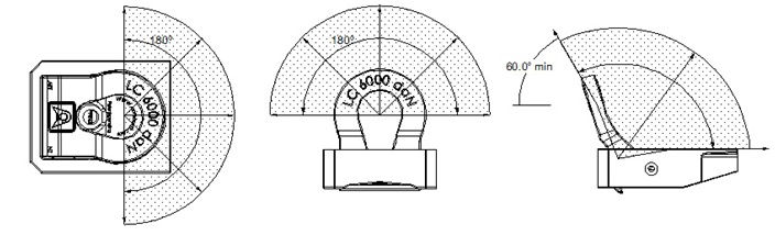
The Armour Load Anchor is designed to restrain a chain or other suitable load bindings. The direction from which a load may be applied is shown below:
The Armour Load Anchor consists of an "eye" for attaching the load binding, a sealing plate (Armour Push plate) and a housing. The Armour Push Plate has no structural function and is loose fitting so that it expels dirt when it is moved either by hand or movement of the vehicle. The eye may be raised by pressing down on the Armour Push Plate through the hinge end of the hole in the eye. For this reason and because the eye swings down at the hinge end it is important that the underside of the housing is left open and clear of obstructions.
The Armour Load Anchor is manufactured from a weldable quenched and tempered cast steel. It is designed for welding to a steel supporting structure made from any grade of weldable structural steel. All welding must be undertaken by a person who is trained and competent at welding using the process and materials chosen and the type of weld in the applicable position. Prior to welding, pre-heat the load anchor housing and adjacent supporting structure. Welding materials must be suitable for welding to the materials from which both the Armour Load Anchor and the supporting structure are made. The supporting structure must be designed by a suitably qualified professional to withstand all the forces imposed on it by the load or loads being supported and all the load anchorage devices installed.
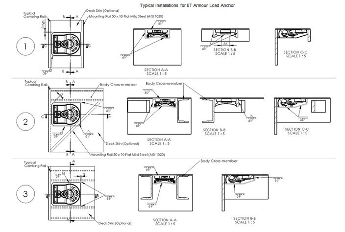
Generally the Armour Load Anchor must be attached by at least the two sides or the two ends or alternatively by the hinge end and one side with "assistance" at the unsupported corner. See overleaf for general details of 3 alternative mounting arrangements.
Ensure you have the correct Armour Load Anchor for the required rating - the Utility Armour Load Anchor has a base which measures approximately 105mm x 108 mm (4.2" x 4.3"). It is the owner's responsibility to ensure that the correct number, location and capacity of load anchor is used to meet the country's legislative requirements.
For a load anchor to be safe when loaded to its maximum load rating the load platform or supporting structure to which the load anchor is attached must be designed and constructed to withstand the forces applied by the load anchor or anchor(s) and load(s). The Armour Load Anchor must be installed in accordance with these instructions and the advice of a suitably qualified professional must be followed with regard to the design of the supporting structure.
The Armour Load Anchor or the supporting structure must be clearly marked or identified with the load rating for which the load anchor is designed and installed. This rating may be less but never more than the rating supplied by the manufacturer of the load anchor.
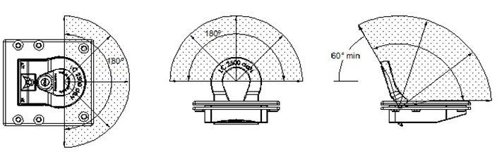
The Armour Load Anchor is designed to restrain a strap or other suitable load bindings. The direction from which a load may be applied is shown below:
The Armour Load Anchor consists of an "eye" for attaching the load binding, a sealing plate (Armour Push plate) , the main housing, and a backing plate. The Armour Push Plate has no structural function and is loose fitting so that it expels dirt when it is moved either by hand or movement of the vehicle. The eye may be raised by pressing down on the Armour Push Plate through the hinge end of the hole in the eye. For this reason and because the eye swings down at the hinge end it is important that the underside of the housing is left open and clear of obstructions.
The Armour Load Anchor is manufactured from a weldable quenched and tempered cast steel, with a galvanized finish. The housing and backing plate each have six (6) corresponding pre-drilled holes. The Load Anchor is designed to be fitted by cutting a hole in the deck (surface of the object being fitted to) using the inside of the backing plate as a template, drilling through the deck so that the housing can be screwed to the backing plate using the screws supplied. Note it is critically important that the deck (surface) to which the Armour Load Anchor being fitted is designed by a suitably qualified professional to withstand all the forces imposed on it by the load or loads being supported and all the load anchorage devices installed.
The Load Anchor can also be welded to a steel deck (surface) or other supporting structure made from any grade of weldable structural steel. All welding must be undertaken by a person who is trained and competent at welding using the process and materials chosen and the type of weld in the applicable position. Prior to welding, clean the galvanizing off the housing and pre-heat the housing and adjacent supporting structure/deck. Welding materials must be suitable for welding to the materials from which both the Armour Load Anchor and the supporting structure are made. The supporting structure/deck must be designed by a suitably qualified professional to withstand all the forces imposed on it by the load or loads being supported and all the load anchorage devices installed. Generally the Armour Load Anchor must be attached by all sides
Ensure you have the correct Armour Load Anchor for the required rating – the 12T Armour Load Anchor measures approximately 140 mm high x 140 mm across x 120 mm along. It is the owner’s responsibility to ensure that the correct number, location and capacity of load anchor is used to adequately restrain the load and meet all legislative requirements.
For a load anchor to be safe when loaded to its maximum load rating the load platform or supporting structure to which the load anchor is attached must be designed and constructed to withstand the forces applied by the load anchor or anchor(s) and load(s). The Armour Load Anchor must be installed in accordance with these instructions and the advice of a suitably qualified professional must be followed with regard to the design of the supporting structure. No responsibility, liability, warranty or claim will be accepted from any party whatsoever for any loss, damage or injury resulting from failure if the Armour Load Anchor is not installed in accordance with these instructions or if the Armour Load Anchor or any of the supporting structure is damaged, corroded or in need of maintenance or if the Armour Load Anchor or supporting structure is subjected to misuse or abuse at any time. No liability will be accepted for any loss or injury occurring during the installation or preparation for installation of the Armour Load Anchor. All personnel must be trained and competent in all the processes and the use of all tools involved in the preparation and installation.
The Armour Load Anchor or the supporting structure must be clearly marked or identified with the load rating for which the load anchor is designed and installed. This rating may be less but never more than the rating supplied by the manufacturer of the load anchor.
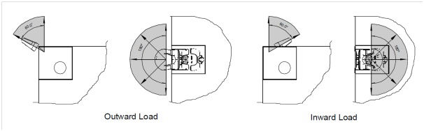
The Armour Load Anchor is designed to restrain chain or other suitable load bindings. The directions from which loads may be applied are shown below:
The Armour Load Anchor consists of an “eye” for attaching the load binding, a sealing plate and a base. The sealing plate has no structural function and is loose fitting so that it expels dirt when it is moved either by hand or movement of the vehicle. The eye may be raised by pressing down on the sealing plate through the hinge end of the hole in the eye.
The Armour Load Anchor base is manufactured from a weldable quenched and tempered cast steel complying with SAC GB/T
ZG-20SiMn. It is designed for welding to a steel supporting structure made from any grade of weldable structural steel. All welding must be undertaken by a person who is trained and competent at welding using the process and materials chosen and the type of weld in the applicable position. Prior to welding, the load anchor housing and adjacent supporting structure must be pre-heated to 200ºC. Welding materials must be suitable for welding to the materials from which both the Armour Load Anchor and the supporting structure are made. The supporting structure must be designed by a suitably qualified professional to withstand all the forces imposed on it by the load or loads being supported and all the load anchorage devices installed.
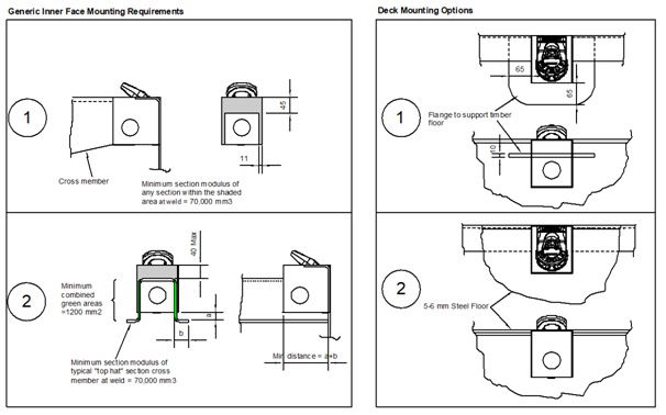
Generally, the Armour Load Anchor must be attached by at least the two sides and the outer face or alternatively by one side and the outer face using a larger cross-member. Examples of these installations are given on page 3. It may also be attached to the inner and outer faces only and if the end of the cross member is attached to the inner face there are minimum strength requirements which are described on page 4. The information on page 4 is for qualified design professionals and is not intended to inform fabricators. All the information given is intended to provide for a 12 Tonne rating. It is possible to install and rate the lashing point to suit lower ratings if 12 Tonne is not required or not practical.
All the information given on these sheets is based on using structural mild steel plate and rolled sections with a minimum yield strength of 300 Mpa.
Installation Examples
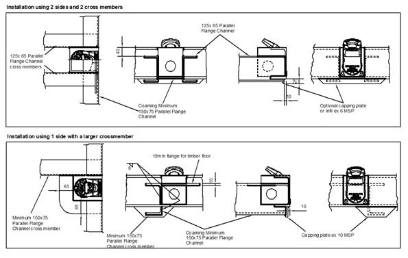
Note - The information provided is intended to assist a qualified design professional. It is not intended as specifications for a fabricator to work to.
The Armour Load Anchor must be installed in accordance with these instructions
The Armour Load Anchor must be installed in accordance with these instructions and the advice of a suitably qualified professional must be followed with regard to the design of the supporting structure. No responsibility, liability, warranty or claim will be accepted from any party whatsoever for any loss, damage or injury resulting from failure if the Armour Load Anchor is not installed in accordance with these instructions, or if the Armour Load Anchor or any of the supporting structure is damaged, corroded or in need of maintenance or if the Armour Load Anchor or supporting structure is subjected to misuse or abuse at any time. No liability will be accepted for any loss or injury occurring during the installation or preparation for installation of the Armour Load Anchor. All personnel must be trained and competent in all the processes and the use of all tools involved in the preparation and installation.
The Owner warrants that it adheres to all relevant local and central government laws and regulations in relation to the use of the Load Anchors. Armour Transport Technologies Ltd (ATT) shall not be liable (whether in contract, tort, including negligence, or otherwise) to the Owner for any loss or damage (including but not limited to direct, indirect or consequential loss or damage) arising from the use of the Load Anchor. For the purposes of this clause ?indirect or consequential loss or damage? includes loss or reduction of business or profits.
The Owner shall indemnify ATT and keep ATT fully and effectively indemnified against all losses, claims, damages, costs, charges, expenses, liabilities, demands, proceedings, and actions which ATT may sustain or incur or which may be brought or established against it by any person and in any case which arise out of or in relation to the use of the Load Anchor by the Owner whether or not by reason of any Act, regulation, common law rule, or in equity or otherwise and whether for damages or for other relief.
Armour Transport Technologies Ltd
Barry Armour
Location